
Quick Answer
A DC fast charging connector must survive 10,000+ mating cycles, 1,000 V and up to 600 A of electrical load, and years of outdoor UV, rain, and dust exposure — while remaining light enough for drivers and service teams to handle comfortably dozens of times per day. Durability and lightweight design are no longer competing goals. Engineering thermoplastics, liquid-cooled copper pin assemblies, and ergonomic handle geometry now let manufacturers such as MIDA Power build CCS1, CCS2, and NACS connectors that reduce handheld weight by 20–40% versus conventional rubberized designs without sacrificing mechanical life. Operators who specify certified, cooled, ergonomically designed connectors report fewer connector-related callouts, less cable strain damage, and a lower total cost of ownership across the charger’s 10+ year service life.
Key Takeaways
- Durability is measurable: verify 10,000+ insertion cycles, IP55 or better ingress protection, and UL 2251 / IEC 62196-3 certification before specifying any DC connector.
- Weight is an operating cost: lighter handles reduce operator fatigue, cable strain, and connector dropout failures over a charger’s 10+ year lifetime.
- Thermal management enables lightness: liquid cooling allows smaller conductors at 500–600 A, cutting connector and cable mass by up to 40%.
- Standards shape the design: CCS1, CCS2, and NACS impose different voltage, current, and locking requirements — select by target market, not by habit.
- Ergonomic design is a durability feature: trigger placement, grip texture, and cable exit angle determine how many cycles a connector survives in real field use.
The Hidden Cost of Connector Failure
Connector failure is one of the most expensive — and most preventable — failure modes in a DC fast charging network. When a coupler wears out, cracks, or loses electrical contact, the entire charging bay goes offline. Revenue stops, the service truck rolls out, and the operator carries the replacement cost. Industry field data from charge point operators consistently ranks connector and cable assemblies among the top warranty replacement line items, with failure drivers dominated by three causes: cable strain at the handle entry, contact pin wear after repeated insertions, and moisture or dust ingress through degraded seals.
The financial impact is larger than the part cost. A typical DC cable and connector assembly costs between $300 and $800 to replace, but the real loss is downtime: a 150 kW charger serving roughly 15–20 sessions per day can lose $200–$500 in daily revenue while the bay is dark. Multiply that across a network of 50–500 stations and a connector design decision worth a few dollars at procurement becomes a six-figure operating cost over the fleet’s lifetime.
This is why durability and ergonomics must be evaluated together. A connector that is technically robust but physically heavy will be dropped, yanked, and twisted — and those mechanical abuses defeat the engineering that made it durable in the first place. The modern answer is a connector that is engineered for both: materials that withstand 10,000+ cycles and a shape, weight, and balance that reduce the human errors that kill connectors early.
What “Durability” Actually Means for a DC Connector
Durability for a DC connector is defined by measurable engineering parameters, not marketing claims. Buyers should evaluate five dimensions before any purchase decision.
Mechanical life. Mating cycles are the headline number. IEC 62196-3 sets the durability expectation for DC connectors at 10,000 insertion/withdrawal cycles, and premium designs reach 20,000+. Every cycle wears the contact surfaces and the latch mechanism, so cycle rating correlates directly with service life. Connector locks and trigger interlocks are tested separately — a broken latch takes the bay offline just as surely as a burned pin.
Electrical performance. Contact resistance is the parameter that determines whether a connector runs cool. A high-quality silver-plated copper alloy contact keeps resistance low and stable across the product’s life; a poorly plated contact degrades quickly, raises temperature rise, and eventually melts the housing. The relevant spec is temperature rise at rated current — responsible designs hold it at ≤50 K above ambient at the rated amperage, and liquid-cooled couplers achieve the same rise at 600 A with far less copper.
Environmental sealing. Ingress protection ratings define survival outdoors: IP54 for splash resistance, IP55 for water jets plus dust protection. Beyond IP, the housing must resist UV degradation, ozone, salt spray in coastal installations, and the temperature swings of a charging plaza in summer asphalt heat. Housing materials and seal compounds determine this, not the logo on the side.
Safety certification. Compliance is non-negotiable for deployment. A connector sold into North America should carry UL 2251 listing; European installations reference IEC 62196-3 with CE marking; many global projects additionally require TÜV certification. Certified connectors have documented failure testing — short-circuit, thermal, and mechanical abuse tests — that uncertified alternatives simply do not have. MIDA Power’s connector range is TUV/CE/UL certified across CCS1, CCS2, and NACS product families.
The Weight Problem: Why Lightweight Matters to Operators
Handle weight directly drives operator fatigue, cable damage, and connector failures. The connector handle is only part of the mass an operator lifts — the cable is the heavier partner. A 5 m cable for a 150 kW charger with 70 mm² conductors can weigh 8–10 kg on its own; a 5 m liquid-cooled 600 A cable comes in around 4–6 kg. Add a heavy connector body and the combined handheld mass approaches 10–12 kg, lifted, positioned, and aligned dozens of times per day.
The consequences are measurable. Repeated lifting of heavy assemblies causes musculoskeletal strain for service staff and charging attendants, which in turn produces rushed insertions, dropped connectors, and forced insertions at bad angles. Every one of those events stresses the cable entry point — the number one mechanical failure location on DC connectors. Cable strain at the strain-relief point, not contact wear, is what most operators actually see in warranty returns.
Lightweight design breaks this loop. A connector body reduced from roughly 1.5 kg to under 1 kg, combined with a properly balanced center of gravity, makes one-hand operation feasible. The operator inserts the connector cleanly, the cable hangs without twisting, and the strain relief does its job. The result is a durability improvement that costs nothing in materials — it comes entirely from geometry and weight engineering.
Materials Science: Building Lighter Connectors That Still Last
The path to a lighter connector is materials engineering, not simply removing material. Four material families dominate modern DC connector construction, and each one trades weight, cost, and durability differently.
Glass-fiber-reinforced polyamide (PA66 + GF) is the workhorse of premium connector housings. It offers a high strength-to-weight ratio, excellent dimensional stability across temperature extremes, and UV-stabilized grades that survive years of direct sunlight. PA66 housings are the reason modern connectors can shed 20–30% of their weight versus older designs while passing impact and crush tests.
PC/ABS blends appear in cost-sensitive designs where thermal demands are moderate. They mold easily and hold color well, but their heat deflection temperature is lower — a poor fit for high-current applications where the housing doubles as a heat path.
Aluminum alloy housings are used in high-power, liquid-cooled couplers where the body must conduct heat away from the contacts. Aluminum acts as both structure and heat sink, and because cooling capacity replaces copper cross-section, the total assembly is often lighter than an uncooled connector rated for the same current.
Rubber overmolding deserves attention because it is a classic weight trap. Overmold improves grip, sealing, and drop resistance, but thick overmold adds grams everywhere. Modern ergonomic designs use thin, patterned overmold only in the grip zone, leaving the rest of the housing exposed for weight savings.
Contact design completes the picture. Silver-plated copper alloy pins are standard; what separates good designs is the pin geometry. Hollow or sleeved pin designs reduce material while preserving current path, and spring-loaded contact designs extend cycle life by maintaining consistent contact pressure as surfaces wear.
Thermal Management: The Bridge Between Durability and Weight
Liquid cooling is the single most effective way to make a high-power connector lighter. The physics is straightforward: conductor cross-section is set by allowable temperature rise, and active cooling removes heat from the contact zone, so the copper can shrink. At 500–600 A, this matters enormously. An air-cooled 600 A connector requires massive pin and cable conductors; a liquid-cooled coupler carries the same current with a fraction of the copper and a dramatically thinner cable.
MIDA Power’s liquid-cooled 600A NACS charging coupler series illustrates the range: the platform covers 16 A to 600 A+, with coolant channels integrated into the handle and temperature sensing that feeds the charger’s derating logic. Because the cooling loop runs through the cable, the entire handheld assembly — connector plus cable — gets lighter and more flexible. Operators gain easier handling, and the station gains the ability to hold high power for extended sessions instead of tapering on thermal limits.
Liquid cooling also protects the connector’s internal components. Lower operating temperatures slow contact oxidation, protect seal compounds, and extend latch and spring life. The cooling system is a durability investment that pays for itself in both throughput and longevity.
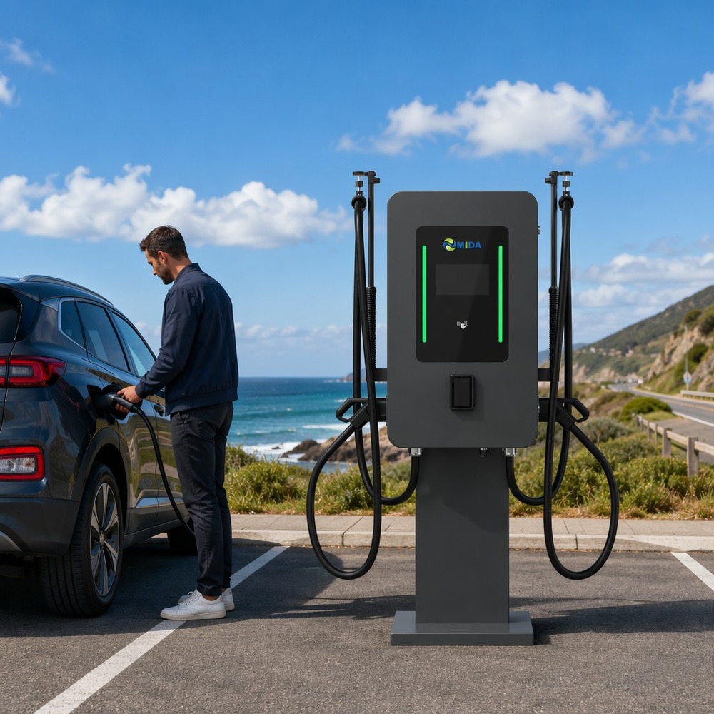
Connector Standards Compared
Choosing the right connector family starts with the charging standard in the target market. The table below summarizes the four major DC connector standards and how their electrical and physical requirements shape durability and weight.
| Standard | Primary markets | Max voltage | Typical DC current | AC support | Liquid-cooled options | Relative handheld weight |
|---|---|---|---|---|---|---|
| CCS1 (Combo 1) | North America, South Korea | 1,000 V | 125–500 A | No (separate J1772 inlet) | 500 A HPC couplers available | Heavier; bulkier DC+AC pin arrangement |
| CCS2 (Combo 2) | Europe, UK, APAC | 1,000 V | 125–600 A | Yes (single inlet AC/DC) | 600 A liquid-cooled couplers available | Medium; lighter than CCS1 at same rating |
| NACS | North America (Tesla ecosystem) | 1,000 V | 80–600 A | Yes (single plug AC/DC) | 600 A liquid-cooled couplers available | Lightest form factor; compact pin layout |
| GB/T | China | 750–1,000 V | 125–250 A | Yes (separate connector) | Emerging | Heavier; larger housing |
Three practical conclusions follow. First, CCS2′s single-inlet AC/DC architecture eliminates a separate AC connector, which simplifies the vehicle-side interface and lets the connector designer optimize a single housing. Second, NACS’s compact pin layout is the reason the standard is the lightest of the four — a factor that contributed to its rapid adoption across North American OEMs. Third, for any standard, liquid cooling is the technology that closes the gap between high current and manageable weight. See our detailed CCS1 vs CCS2 connector standards comparison for market-by-market guidance.
Designing for the Operator: Ergonomic Connectors in Practice
Ergonomic design is a reliability feature because it reduces the human-induced stress that kills connectors. The same 10,000-cycle connector survives 10,000 cycles in a lab and 4,000 in the field if operators are fighting the handle every session. Ergonomic engineering addresses four specific touchpoints.
Grip geometry. The handle should fill the palm with a balanced center of gravity so the connector hangs naturally when held. A top-heavy handle forces the operator to over-grip, which translates into insertion misalignment over time.
Trigger and interlock placement. The release trigger must sit under the index or middle finger in the natural grip position, with a short, positive travel. Operators who must search for the trigger or stretch to reach it will force the latch and accelerate wear.
Cable exit angle. The cable should exit the handle at an angle that matches the natural approach to a vehicle inlet — typically 45–90 degrees depending on station layout — with a reinforced strain-relief cone. Straight-exit connectors are the most common cause of cable-side failures.
Visual feedback. Light-guide status LEDs on the handle communicate charging state at a glance, reducing unnecessary insertions and removals. Every avoided cycle extends the connector’s mechanical life.
MIDA Power applies these principles across its CCS2 plug, UL-rated CCS1 combo connector, and NACS DC connector lines, with housings designed for one-hand operation and cable assemblies engineered as an integrated system rather than an afterthought.
What to Specify When Buying DC Connectors
Buy connectors on verified specifications, not samples. Use this checklist when evaluating suppliers for a charging network or OEM program.
- Certification for the target market — UL 2251 for North America, IEC 62196-3/CE for Europe, TÜV where required; confirm the certificate covers your exact model.
- Rated current with defined ambient — 125 A, 200 A, 300 A, or 600 A ratings must state the ambient temperature and allowable temperature rise; 40 °C ambient with ≤50 K rise is a solid baseline.
- Mechanical life and sealing — minimum 10,000 mating cycles and IP55 ingress protection for outdoor plazas.
- Cable assembly integration — specify cable length, jacket material, bending radius, and strain relief as part of the connector purchase; mismatched cable and connector designs fail early.
- Liquid cooling interface — for 500 A+ systems, confirm coolant compatibility, flow requirements, and temperature sensor integration with your charger platform.
- OEM/ODM flexibility — custom housings, branding, cable lengths, and connector-vehicle compatibility testing matter for network operators with proprietary hardware. MIDA Power offers professional OEM/ODM services with 10+ years of manufacturing experience across AC/DC connectors and charging stations.
FAQ
1. How many charging cycles does a DC fast charging connector last?
Premium DC connectors are rated for 10,000+ insertion/withdrawal cycles per IEC 62196-3, with top-tier designs reaching 20,000 cycles. Field life depends on operator handling, cable strain, and environmental conditions; ergonomic, balanced designs consistently outlive awkward, heavy ones.
2. What is the difference between CCS1 and CCS2 connectors?
CCS1 (Combo 1) serves North America and South Korea with a separate J1772 AC inlet, while CCS2 (Combo 2) serves Europe, the UK, and much of APAC with a single inlet for both AC and DC charging. CCS2 connectors are generally lighter at equal ratings and support higher current density.
3. Are NACS connectors lighter than CCS connectors?
Yes. NACS uses a compact pin layout with a single plug for AC and DC, which reduces housing size and weight compared to CCS1 and CCS2 at equivalent current ratings. Liquid-cooled 600 A NACS couplers push the weight advantage further.
4. How does liquid cooling reduce connector weight?
Liquid cooling removes heat directly from the contact zone, so conductor cross-sections shrink while maintaining the same current rating. Less copper in the pins and cable means a lighter handheld assembly and a thinner, more flexible cable — a 20–40% mass reduction at 500–600 A.
5. Which certifications should a DC charging connector carry?
For global deployments, specify UL 2251 (North America), IEC 62196-3 with CE marking (Europe), and TÜV certification where project contracts require it. Certificates must match the exact model number being supplied.
6. Can a single connector handle both AC and DC charging?
CCS2 and NACS connectors support both AC and DC through a single inlet; CCS1 requires a separate J1772 connector for AC charging, and GB/T uses a separate AC connector as well. For sites serving mixed vehicle fleets, standards with dual-mode support simplify inventory.
7. How do I choose between a 200 A and a 600 A connector?
Match the connector to the charger’s maximum output and future upgrade path: 200 A covers 150–200 kW class chargers, while 500–600 A liquid-cooled couplers are required for 350 kW+ ultra-fast platforms. Buying a cooled connector one class above current needs protects the investment when power upgrades arrive.
Post time: Aug-18-2026